CFD Workflow for Airflow Simulation Around a Pipe (Detailed)
Overview
This report documents the end-to-end CFD workflow used to simulate steady incompressible airflow around a pipe inside a rectangular domain.
1) Geometry Creation (Fusion 360)
The CAD workflow was:
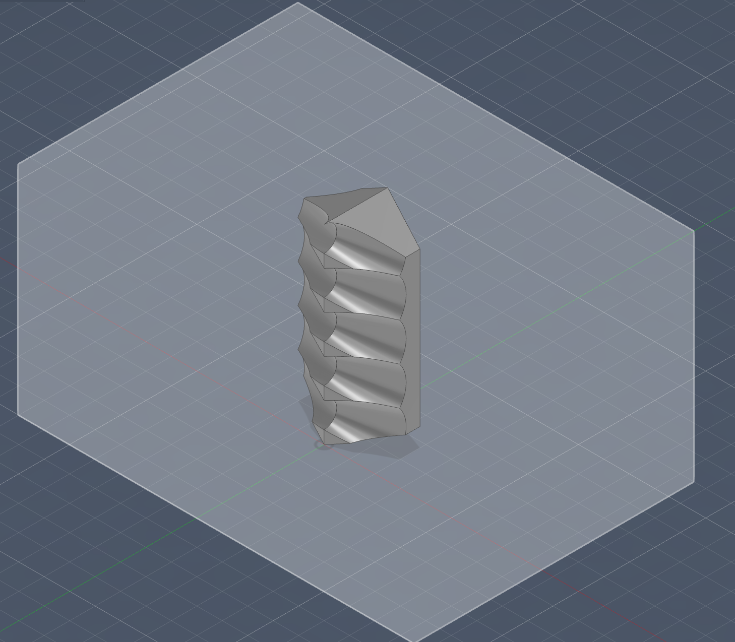
- Create the pipe solid.
- Create a surrounding box representing the external air domain.
- Subtract the pipe from the box to obtain the fluid volume.
This produced the computational domain for OpenFOAM, where the pipe behaves as an internal obstacle.
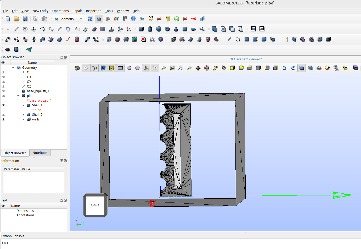
2) Geometry Export and Boundary Grouping (Salome)
Because STL export does not preserve CAD face metadata, boundary zones were rebuilt in Salome by creating surface groups:
inletoutletwalls
These groups were exported as STL surfaces and used by snappyHexMesh.
3) Mesh Generation in OpenFOAM
Meshing used:
blockMeshfor background meshsnappyHexMesh -overwritefor geometry fitting/refinementcheckMeshfor mesh quality verification
3.1 Background mesh (blockMeshDict)
- Domain bounds (m):
- min =
(-0.08 -0.05 -0.01) - max =
(0.02 0.07 0.09)
- min =
- Base cell counts:
(20 20 20) - Grading:
simpleGrading (1 1 1)
This was chosen as a moderate base resolution that remains stable on 16 GB RAM.
3.2 Snappy settings (snappyHexMeshDict)
Final robust settings:
castellatedMesh true;snap false;addLayers false;
Key memory-control parameters:
maxLocalCells 120000;maxGlobalCells 250000;nCellsBetweenLevels 2;minRefinementCells 10;maxLoadUnbalance 0.10;
Surface refinement:
inlet level (2 2);outlet level (2 2);walls level (2 2);resolveFeatureAngle 60;
Region refinement:
refinementBox mode inside;refinementBox level 1;
Robust geometry selection:
insidePoint (-0.03 0 0);
3.3 Why these values were selected
Earlier runs with stronger refinement and larger effective feature growth caused excessive memory use and froze the machine. The final settings above were selected to:
- preserve resolution near surfaces,
- cap global mesh growth hard,
- avoid expensive snapping/layer operations initially,
- guarantee reproducible runtime on a 16 GB system.
3.4 Final mesh quality (checkMesh)
Final mesh statistics:
- Cells:
116574 - Faces:
382163 - Points:
149188 - Boundary patches:
3
Patch topology in final mesh:
box(wall):1968facesoutlet(patch):5032faceswalls(wall):32952faces
Quality highlights:
- Max non-orthogonality:
27.5052(OK) - Max skewness:
0.333333(OK) - Max aspect ratio:
1.2 - Result: Mesh OK
4) Simulation Setup (simpleFoam)
Steady incompressible RANS simulation in OpenFOAM 11.
4.1 Solver control (system/controlDict)
application simpleFoam;startTime 0;endTime 500;deltaT 1;(iteration counter for steady solver)writeInterval 500;(write only final time)
4.2 Turbulence and fluid properties
constant/momentumTransport:
simulationType RAS;model kOmegaSST;turbulence on;
constant/physicalProperties:
viscosityModel constant;nu = 1.5e-05 m2/s
4.3 Boundary conditions used
Note: due to final snappy patching, the solved mesh uses box, outlet, and walls.
Velocity U (0/U)
- Internal field:
uniform (5 0 0)m/s box:fixedValue (5 0 0)outlet:inletOutlet,inletValue (0 0 0)walls:noSlip
Pressure p (0/p)
- Internal field:
uniform 0 box:zeroGradientoutlet:fixedValue 0walls:zeroGradient
Turbulence fields
k (0/k):
- Internal:
0.1 box:fixedValue 0.1outlet:inletOutletwithinletValue 0.1walls:kqRWallFunction
omega (0/omega):
- Internal:
10 box:fixedValue 10outlet:inletOutletwithinletValue 10walls:omegaWallFunction
nut (0/nut):
- Internal:
0 box/outlet:calculatedwalls:nutkWallFunction
4.4 Numerics
fvSchemes:
- Steady state time discretization
- Bounded upwind for
kandomega linearUpwindV grad(U)for momentum convection
fvSolution:
- Pressure:
GAMG - U/k/omega:
smoothSolver+GaussSeidel - SIMPLE with
nNonOrthogonalCorrectors 0,consistent yes - Relaxation:
U 0.9,k 0.7,omega 0.7
5) Run Execution and Troubleshooting
Run command:
simpleFoamOpenFOAM 11 internally redirects this to:
foamRun -solver incompressibleFluidThis is expected behavior in current OpenFOAM versions.
Run completed successfully to Time = 500 with exit code 0.
Observed during run:
- Stable residual progression
- Occasional
bounding kmessages (small local clipping), but no divergence - Successful final write of solution fields at time
500
6) Post-Processing Verification (Numerical)
To confirm the solution is physically non-trivial (not just mesh), scalar checks were run at time 500:
volAverage(U) = (4.89468 -0.00457188 -8.83707e-05)volAverage(p) = -24.3051cellMin(U) = (-33.875 -30.6823 -33.3505)cellMax(U) = (15.7593 22.5352 23.8255)cellMin(p) = -375.458cellMax(p) = 464.906
These values confirm computed flow and pressure gradients are present in the solved field.
7) ParaView Workflow Notes
If only a plain box appears in ParaView, common causes are:
- Time slider left at
0instead of500 internalMeshdisabled in OpenFOAM reader- Coloring left on
Solid Colorinstead ofU,p, etc.
Tools Used
- Fusion 360 (CAD)
- Salome (surface grouping)
- OpenFOAM 11:
blockMeshsnappyHexMeshcheckMeshsimpleFoam(redirected tofoamRun -solver incompressibleFluid)
- ParaView
Key Learnings
- STL-based workflows require explicit boundary group reconstruction.
- Mesh RAM usage is dominated by refinement controls; hard cell limits are essential on limited-memory hardware.
- Snapping and layers are useful but should be introduced after a stable baseline mesh exists.
- Always verify solved fields numerically (
volAverage, min/max), not only visually.
Conclusion
A complete and stable CFD workflow was executed from CAD to converged steady-state solution and visualization. The final configuration balances mesh quality and computational robustness for a 16 GB workstation, while producing valid, non-uniform flow and pressure fields around the pipe.